When designing high-speed or high-current electronic systems, power integrity becomes a critical factor. Voltage ripple, transient spikes, and electromagnetic interference can cause unpredictable behavior or even permanent damage. To prevent these issues, engineers rely on simulation tools before committing to PCB fabrication. One of the most accessible and powerful tools available is LTspice.
Many designers use LTspice to model decap and bondwire inductance because it allows detailed analysis of parasitic elements that significantly impact real-world performance. Decoupling capacitors (decaps) are not ideal components; they include parasitic resistance and inductance. Similarly, bondwires inside integrated circuits introduce inductance that affects switching behavior and transient response.
Understanding how to accurately represent these non-ideal characteristics in LTspice helps engineers predict voltage droop, ringing, and resonance effects with greater confidence. This article provides a practical, human-centered walkthrough on how to build realistic simulation models and interpret results effectively.
Understanding Decoupling Capacitors in Real Circuits
Before diving into simulation, it’s important to understand what makes a decoupling capacitor non-ideal.
What Is a Decap?
A decoupling capacitor is placed near an integrated circuit’s power pins to:
-
Supply transient current during switching events
-
Reduce voltage ripple
-
Filter high-frequency noise
-
Improve overall power integrity
However, real capacitors are not purely capacitive. They include:
-
Equivalent Series Resistance (ESR)
-
Equivalent Series Inductance (ESL)
These parasitic elements influence impedance across frequency and can cause resonance peaks.
Why Bondwire Inductance Matters
Inside IC packages, bondwires connect the silicon die to external pins. These tiny wires may appear insignificant, but they introduce measurable inductance.
Typical bondwire inductance values range from:
-
0.5 nH to 3 nH per wire
At high switching speeds, even 1 nH can generate noticeable voltage spikes using:
V=LdidtV = L \frac{di}{dt}
For example, with a 1 nH inductance and a current slew rate of 1 A/ns, you can see a 1 V spike — a serious concern in low-voltage systems.
This is precisely why engineers use LTspice to model decap and bondwire inductance during early design stages.
How to Use LTspice to Model Decap and Bondwire Inductance
Now let’s walk through the practical implementation.
Step 1: Modeling a Realistic Decoupling Capacitor in LTspice
1. Create the Basic Capacitor
Start by placing a capacitor component:
-
Press F2
-
Select the capacitor symbol
-
Place it in your schematic
Set its nominal capacitance (e.g., 0.1 µF).
2. Add ESR to the Decap Model
In LTspice, ESR can be modeled by placing a resistor in series with the capacitor.
Example:
-
Capacitor: 0.1 µF
-
ESR: 10 mΩ
Place a resistor in series with the capacitor and assign the appropriate value.
3. Add ESL to Represent Parasitic Inductance
To model ESL:
-
Add a small inductor in series (e.g., 0.5 nH to 2 nH)
Your final model becomes:
Resistor → Inductor → Capacitor (all in series)
This structure accurately reflects the real-world behavior of a decoupling capacitor.
Step 2: Modeling Bondwire Inductance in LTspice
Representing the Bondwire
Bondwire inductance can be modeled using a simple inductor placed between:
-
Voltage source and IC power pin
or -
Decoupling network and load
Example:
-
Add a 1 nH inductor to represent a single bondwire
-
If multiple bondwires exist in parallel, divide inductance accordingly
For two parallel bondwires:
Ltotal=L2L_{total} = \frac{L}{2}
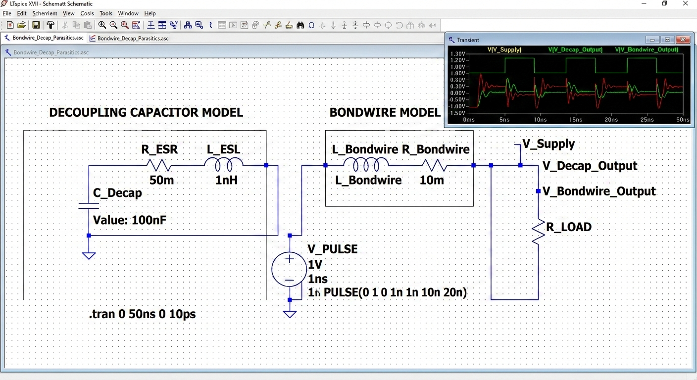
Building a Complete Power Integrity Simulation
To effectively use LTspice to model decap and bondwire inductance, create a test circuit that includes:
-
Voltage source
-
Bondwire inductance
-
Decoupling capacitor network
-
Load (pulsed current source)
Example Setup
-
Voltage Source: 1.2 V DC
-
Bondwire Inductor: 1 nH
-
Decap Model:
-
0.1 µF
-
10 mΩ ESR
-
0.8 nH ESL
-
-
Load: Pulsed current source (0 to 2 A step)
Run a transient simulation:
This allows you to observe voltage droop and ringing.
Observing Ringing and Resonance
When you use LTspice to model decap and bondwire inductance, one of the most important behaviors to analyze is resonance.
Resonant frequency is approximately:
f=12πLCf = \frac{1}{2\pi\sqrt{LC}}
If bondwire inductance and capacitor ESL combine with capacitance, you may see:
-
Underdamped ringing
-
Overshoot
-
Sustained oscillation
By adjusting ESR, you can study damping effects.
Frequency Domain Analysis
Transient simulations are helpful, but frequency response provides deeper insight.
Running an AC Sweep
Add this directive:
Plot impedance across frequency to identify:
-
Self-resonant frequency (SRF)
-
Impedance minimum
-
High-frequency inductive region
This helps determine whether your decoupling network is effective across your target bandwidth.
Modeling Multiple Decoupling Capacitors
In real designs, engineers use capacitor arrays:
-
10 µF bulk capacitor
-
1 µF mid-frequency capacitor
-
0.1 µF high-frequency capacitor
Each should include ESR and ESL.
When you use LTspice to model decap and bondwire inductance in a multi-capacitor setup, you may observe:
-
Anti-resonance peaks
-
Impedance spikes between capacitors
To reduce anti-resonance:
-
Vary capacitor values
-
Adjust ESR
-
Minimize ESL
Advanced Techniques for Better Accuracy
Using Manufacturer SPICE Models
Many capacitor manufacturers provide SPICE models with:
-
Frequency-dependent ESR
-
Detailed parasitic modeling
Importing these models improves simulation realism.
Modeling PCB Trace Inductance
Bondwire inductance is only part of the picture. PCB traces also contribute inductance.
Rule of thumb:
-
~1 nH per millimeter (approximate)
Add small inductors to represent trace effects.
Simulating Worst-Case Conditions
To fully use LTspice to model decap and bondwire inductance effectively:
-
Increase load step current
-
Reduce ESR
-
Increase switching speed
This reveals system margins.
Common Mistakes to Avoid
-
Ignoring ESL entirely
-
Using ideal capacitors
-
Forgetting parallel inductance reduction
-
Overlooking anti-resonance
-
Not verifying time-step resolution
Simulation timestep should be small enough to capture high-frequency ringing.
Practical Design Insights
When simulation results show excessive ringing:
-
Reduce bondwire inductance (choose better package)
-
Add more high-frequency decaps
-
Increase ESR slightly for damping
-
Improve PCB layout
Simulation is not just theoretical — it informs real-world layout decisions.
Benefits of Using LTspice for Power Integrity Modeling
Engineers prefer LTspice because:
-
It is free and powerful
-
It handles transient and AC analysis well
-
It supports parametric sweeps
-
It allows behavioral sources
-
It is widely trusted in the industry
By learning to use LTspice to model decap and bondwire inductance accurately, you gain the ability to predict system behavior before hardware testing.
Real-World Example: High-Speed FPGA Power Rail
Consider a 1 V FPGA core rail switching 5 A within nanoseconds.
Without modeling:
-
Unexpected voltage droop occurs
-
EMI increases
-
System instability appears
By simulating decap ESR/ESL and bondwire inductance:
-
Voltage ripple can be minimized
-
Capacitor placement can be optimized
-
Package selection becomes data-driven
This prevents costly PCB revisions.
How Accurate Is LTspice Modeling?
While simulations cannot perfectly match reality, they provide:
-
Early risk detection
-
Resonance prediction
-
Comparative analysis between designs
-
Insight into transient behavior
Accuracy depends on:
-
Correct parasitic values
-
Realistic load models
-
Proper timestep settings
When used thoughtfully, LTspice becomes an essential engineering tool rather than just a schematic editor.
Conclusion: Mastering How to Use LTspice to Model Decap and Bondwire Inductance
Power integrity problems rarely announce themselves politely. They appear as intermittent resets, strange EMI signatures, or unexplained voltage spikes. The difference between a robust design and a problematic one often lies in how well parasitic elements were understood during the design phase.
Learning how to use LTspice to model decap and bondwire inductance allows engineers to move beyond idealized assumptions and embrace realistic simulation. By incorporating ESR, ESL, bondwire inductance, and PCB trace effects, designers can accurately predict resonance, ringing, and transient droop.
The effort invested in simulation pays off in fewer board revisions, improved reliability, and better overall performance. In modern high-speed electronics, modeling parasitics is not optional — it is essential.
Frequently Asked Questions (FAQs)
1. Why should I model bondwire inductance in LTspice?
Bondwire inductance significantly affects transient voltage spikes, especially in high-speed switching circuits. Even small inductance values can cause substantial overshoot due to high current slew rates.
2. What is the typical ESL value of a decoupling capacitor?
ESL typically ranges from 0.5 nH to 2 nH for small ceramic capacitors, depending on package size and mounting layout.
3. Can I use ideal capacitors in LTspice for power integrity simulation?
No. Ideal capacitors ignore ESR and ESL, which leads to unrealistic results and hides resonance effects.
4. How do I reduce anti-resonance in a decoupling network?
You can reduce anti-resonance by varying capacitor values, adding damping (ESR), or minimizing inductance in layout and package selection.
5. Is LTspice accurate enough for professional power integrity analysis?
Yes, when realistic parasitic parameters and proper simulation settings are used, LTspice provides highly valuable insight for professional design validation.